drawing 3d shapes on isometric paper

Some 3D shapes are using the isometric drawing method. The blackness dimensions are the true lengths every bit establish in an orthographic projection. The red dimensions are used when drawing with the isometric drawing method. The same 3D shapes drawn in isometric projection would appear smaller; an isometric projection will show the object's sides foreshortened, by approximately 80%.
Isometric projection is a method for visually representing three-dimensional objects in two dimensions in technical and engineering drawings. Information technology is an axonometric projection in which the 3 coordinate axes appear equally foreshortened and the bending between any two of them is 120 degrees.
Overview [edit]

Isometric drawing of a cube

Camera rotations needed to achieve this perspective

Nomenclature of Isometric projection and some 3D projections
The term "isometric" comes from the Greek for "equal mensurate", reflecting that the scale along each axis of the projection is the same (different some other forms of graphical projection).
An isometric view of an object can be obtained past choosing the viewing direction such that the angles between the projections of the 10, y, and z axes are all the aforementioned, or 120°. For example, with a cube, this is washed by first looking direct towards one face. Side by side, the cube is rotated ±45° about the vertical centrality, followed by a rotation of approximately 35.264° (precisely arcsin 1⁄ √three or arctan 1⁄ √2 , which is related to the Magic bending) about the horizontal axis. Note that with the cube (encounter paradigm) the perimeter of the resulting 2nd drawing is a perfect regular hexagon: all the black lines have equal length and all the cube'southward faces are the same expanse. Isometric graph paper can be placed under a normal piece of drawing newspaper to help achieve the effect without calculation.
In a like way, an isometric view tin be obtained in a 3D scene. Starting with the photographic camera aligned parallel to the flooring and aligned to the coordinate axes, information technology is first rotated vertically (around the horizontal axis) past about 35.264° as in a higher place, then ±45° effectually the vertical axis.
Another way isometric projection can be visualized is by because a view within a cubical room starting in an upper corner and looking towards the opposite, lower corner. The x-centrality extends diagonally downward and correct, the y-axis extends diagonally downwards and left, and the z-axis is straight up. Depth is also shown by top on the image. Lines drawn along the axes are at 120° to one another.
In all these cases, as with all axonometric and orthographic projections, such a photographic camera would demand a object-space telecentric lens, in lodge that projected lengths not modify with distance from the photographic camera.
The term "isometric" is often mistakenly used to refer to axonometric projections, generally. There are, however, actually three types of axonometric projections: isometric, dimetric and oblique.
Rotation angles [edit]
From the two angles needed for an isometric projection, the value of the second may seem counterintuitive and deserves some further explanation. Let's first imagine a cube with sides of length 2, and its center at the axis origin, which means all its faces intersect the axes at a altitude of 1 from the origin. We tin can calculate the length of the line from its centre to the middle of whatever edge as √2 using Pythagoras' theorem . By rotating the cube by 45° on the x-axis, the point (one, 1, 1) volition therefore go (one, 0, √two ) equally depicted in the diagram. The 2nd rotation aims to bring the aforementioned signal on the positive z-axis and then needs to perform a rotation of value equal to the arctangent of 1⁄ √2 which is approximately 35.264°.
Mathematics [edit]
There are eight different orientations to obtain an isometric view, depending into which octant the viewer looks. The isometric transform from a point a x,y,z in 3D space to a point b 10,y in 2D space looking into the starting time octant tin be written mathematically with rotation matrices as:

where α = arcsin(tan 30°) ≈ 35.264° and β = 45°. As explained above, this is a rotation around the vertical (hither y) axis by β, followed by a rotation effectually the horizontal (here 10) axis by α. This is then followed by an orthographic projection to the xy-airplane:

The other 7 possibilities are obtained by either rotating to the opposite sides or not, and and then inverting the view direction or not.[ane]
History and limitations [edit]
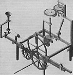
Optical-grinding engine model (1822), drawn in thirty° isometric.[two]

Beginning formalized past Professor William Farish (1759–1837), the concept of isometry had existed in a rough empirical form for centuries.[3] [4] From the center of the 19th century, isometry became an "invaluable tool for engineers, and presently thereafter axonometry and isometry were incorporated in the curriculum of architectural training courses in Europe and the U.S."[5] According to Jan Krikke (2000)[6] all the same, "axonometry originated in China. Its function in Chinese art was like to linear perspective in European art. Axonometry, and the pictorial grammar that goes with it, has taken on a new significance with the advent of visual computing".[6]

An example of the limitations of isometric projection. The meridian difference between the red and blue assurance cannot be determined locally.
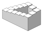
The Penrose stairs depicts a staircase which seems to ascend (anticlockwise) or descend (clockwise) yet forms a continuous loop.
As with all types of parallel project, objects fatigued with isometric projection do not announced larger or smaller as they extend closer to or away from the viewer. While advantageous for architectural drawings where measurements need to be taken straight, the result is a perceived distortion, every bit unlike perspective projection, information technology is not how human being vision or photography normally work. It too can easily effect in situations where depth and altitude are hard to judge, as is shown in the illustration to the right. This tin appear to create paradoxical or impossible shapes, such as the Penrose stairs.
Usage in video games and pixel art [edit]
Isometric video game graphics are graphics employed in video games and pixel art that use a parallel projection, simply which angle the viewpoint to reveal facets of the environment that would otherwise not be visible from a meridian-down perspective or side view, thereby producing a three-dimensional effect. Despite the name, isometric estimator graphics are not necessarily truly isometric—i.e., the ten, y, and z axes are non necessarily oriented 120° to each other. Instead, a diverseness of angles are used, with dimetric projection and a 2:i pixel ratio being the most common. The terms " 3⁄four perspective", " three⁄4 view", "2.5D", and "pseudo 3D" are also sometimes used, although these terms can carry slightly different meanings in other contexts.
Once mutual, isometric project became less and so with the advent of more powerful 3D graphics systems, and as video games began to focus more than on action and individual characters.[7] However, video games utilizing isometric projection—especially calculator role-playing games—take seen a resurgence in recent years within the indie gaming scene.[7] [viii]
See too [edit]
- Graphical projection
References [edit]
- ^ Ingrid Carlbom; Joseph Paciorek; Dan Lim (December 1978). "Planar Geometric Projections and Viewing Transformations". ACM Calculating Surveys. 10 (iv): 465–502. CiteSeerXten.1.one.532.4774. doi:10.1145/356744.356750. S2CID 708008.
- ^ William Farish (1822) "On Isometrical Perspective". In: Cambridge Philosophical Transactions. 1 (1822).
- ^ Barclay Grand. Jones (1986). Protecting historic architecture and museum collections from natural disasters. University of Michigan. ISBN 0-409-90035-iv. p.243.
- ^ Charles Edmund Moorhouse (1974). Visual messages: graphic communication for senior students.
- ^ J. Krikke (1996). "A Chinese perspective for cyberspace? Archived 2016-02-05 at the Wayback Machine". In: International Institute for Asian Studies Newsletter, nine, Summer 1996.
- ^ a b Jan Krikke (2000). "Axonometry: a matter of perspective". In: Computer Graphics and Applications, IEEE Jul/Aug 2000. Vol xx (four), pp. 7–11.
- ^ a b Signor, Jeremy (2014-12-xix). "Retronauts: The Connected Relevance of Isometric Games". usgamer.cyberspace. Gamer Network. Retrieved 2017-04-01 .
- ^ Vas, Gergo (2013-03-18). "The All-time-Looking Isometric Games". kotaku.com. Gizmodo Media Group. Retrieved 2017-04-01 .
External links [edit]
- Isometric Project
Source: https://en.wikipedia.org/wiki/Isometric_projection
0 Response to "drawing 3d shapes on isometric paper"
Post a Comment